
I. Cyclic Voltammetry
Introduction
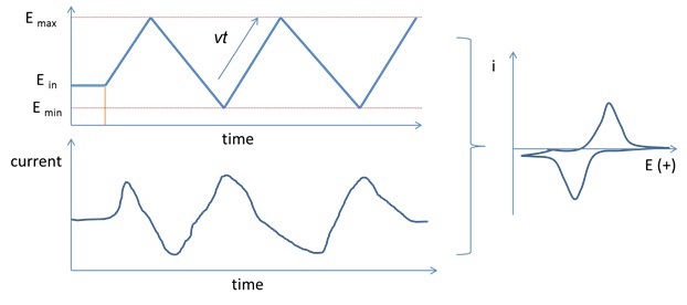
Cyclic voltammetry (CV) is a broadly used electrochemical technique for electrochemical mechanistic study and quantitative analysis. This technique provides accurate measurement on redox potential, mass transfer, and kinetics of (an) redox reaction(s). CV uses a linearly scanned potential of a working electrode between two potential limits Emax and Emin relative to a reference electrode while collecting the current signal drained from the working electrode to a counter electrode. Both current and electrode potential are recorded as a function of time, and then the data can be report as current as a function of potential by eliminating time because time is linear function of electrode potential
E=Ein +/- vt (1)
Ein is the initial electrode potential of a CV. It is usually the rest potential or open circuit potential (OCP) of the working electrode. Many commercial echem instrument can measure OCP of a working electrode automatically. OCP can also be estimated by the potential difference of a working electrode and a reference electrode using a voltameter. +/- sign of equation 1 is dependent on the scan direction of a CV. + is used for positive scan direction and – is used for negative scan direction. As shown in Figure 1, a CV starts scanning from its Ein positively toward Emax and reverses at Emax toward Emin at a scan rate of v. The linear scan be repeated several cycles in order to receive a stable CV.
CV can provide accurate measurement of reaction mechanisms, rates of oxidation and reduction processes, electrode surface area and diffusion constant etc. A CV scan generates an oxidized species during the forward scan and then probing the produced oxidized species with the reverse scan or subsequent cycles. The stability of the produced oxidized species can be detected by varying the scan rate. Unstable species can be detected by improving the scan rate. A 3-electrode configuration is used for CV collection, including a working electrode, reference electrode, and a counter electrode.
- Electrodes for CV measurement.
Working electrode is typically made of chemically inert conductive material such as platinum, Au and glassy carbon. A reference electrode, typically AgCl or calomel, is used to estimate the potential of a working electrode by measuring the potential difference of the working and the reference, and the reference electrode potential must remain stable in CV measurement. A counter electrode is employed to form a complete cycle of charge flow from a working electrode. The counter electrode’s role is essentially to ensure that current does not run through the reference electrode by providing another half reaction corresponding to the one at the working electrode.
If the kinetic parameter electron transfer rate k0 is sufficiently fast for a reaction
O + ne = R (2)
And there is no homogenous reaction and surface adsorption of any reactant and product. This reaction can maintain a Nernstian equilibrium at the electrode surface and we call this kind of reaction as reversible system. It peak current, ip (in amperes), for such reversible system is given by
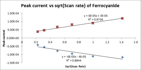
ip=(2.69x10⁵)n3/2AD1/2v1/2CO (3)
where n is equal to the number of electrons gained in the reduction, A is the surface area of the working electrode in cm2, D is the diffusion coefficient, v is the sweep rate, and Co is the molar concentration (mole/cm3) of O in the bulk solution.
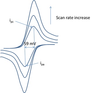
The peak potential is independent of sweep rate and the anodic and cathodic peak potential distance of a reversible system is around 59/n mV.
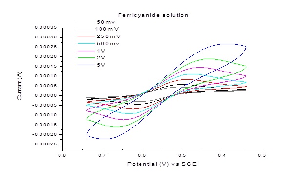
Example 1: CV and peak current dependence on scan rate for 10 mM aqueous solution of K3Fe(CN)6 in 0.1 M Na2SO4
For irreversible system, the peak current and potential positions are affected by reaction kinetics and mechanism. For example, the oxidation peak will decrease in its current intensity if the reduced species are unstable. The peak-peak splitting is more than 59 mV if the charge transfer rate is sluggish for a redox species.
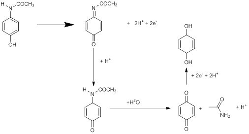
Example 2: CV of 10 mM acetaminophen (AAPH MW: 151.169 g/mol) (active ingredient in Tylenol) in 0.1 M Na2SO4 .
Detailed redox reaction mechanism of AAPH is show below:
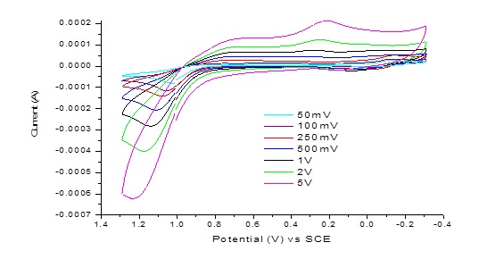
Note: All above experimental data were taken by students from Dr. Pan’s electrochemistry class in Fall 2014.
II. Rotating Disc Electrode for Kinetic studies
Background and introduction
CV is usually done at steady-state without agitating the solution while keeping redox species in diffusion controlled. Under such condition, the redox diffusion layer grows as a function of time and there is no linear diffusion layer to reach a limiting current. The duck shape current response in a CV curve can be explained by such nonlinear mass transfer layer growth as the electrode potential is scanned. Sophisticated digital simulation has to be taken in order to extract useful information such as diffusion constant. Many hydrodynamic methods, in which solution moves toward the electrode along a well-defined flow pattern, may simplify this case by providing a linear growth or a constant diffusion layer so that a limiting current region can be reached. The rotated disk electrode technique is one of the hydrodynamic methods. This technique works by rotating a working electrode at constant speed to let redox species diffuse towards the working electrode surface while potential scan is applied like regular cyclic voltammetry. The higher the rotating speed the thinner the mass transfer layer thickness to produce a higher current density.
Depending on the actual reversibility of a reaction, i-E curves of RDE system can be used to measure the kinetics and mass transfer parameters easily (Figure 3).
The current can reach a limiting current iL at a large over potential region because the redox concentration beyond the diffusion layer remains constant. And the limiting current is defined by
io, L= nFAmoCo (1)
where Co is the bulk concentration of redox molecule O and mo is the mass transfer coefficient, A is electrode surface area and n is number is charge transferred for a half reaction O + neà R. mo is a function of diffusion coefficient of O and time. For a rotating disk electrode, the treatment of steady-state, mass transfer-controlled electrode reactions applies to produce
mo=0.62Do2/3ω1/2ν-1/6 (2)
Do is the diffusion coefficient (cm2/s), ω is the angular velocity of the rotating disk (s-1, 2πf, f is the frequency if the rotating disk or rounds per second), ν is the kinematic viscosity (ν=viscosity η/density d; for aqueous solution ν~0.010 cm2/s).
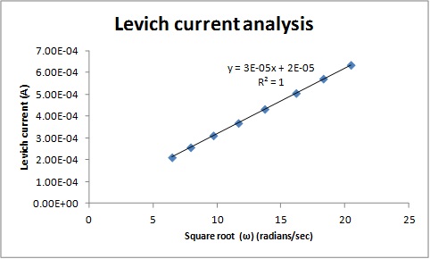
Therefore the obtained limiting current for such rotating disk is given by:
io, L= nFAmoCo=0.62nFADo2/3ω1/2ν-1/6Co (3)
This is the famous Levich equation.
the relationship between diffusion layer thickness d and mo is given by
Mo=Do/d (4)
We can calculate d by using Do/mo to estimate the diffusion layer thickness in a rotating disc experiment.
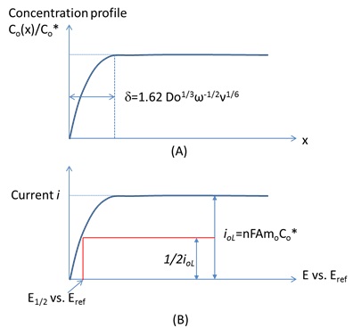
As shown in Figure4A, the diffusion layer thickness is given by
d=1.62 Do1/3ω-1/2ν1/6 (5)
For Nernst reactions where charge transfer rate are infinite large, only mass transfer plays a role.
By taking the current-potential data shown in Figure 4B, we can measure E1/2 which is given by
E1/2=E0O/R + RT/nFln(DR/Do)2/3 (6)
For totally irreversible one step, one electron reaction,
i=FAkfCo(x=0)=FAk0exp[-αf(E-E0’)] Co(x=0) (7)
K0 is the standard rate constant for charge transfer as we discussed in echem kinetics previously. α is the charge transfer coefficient. Co(x=0) is the surface concentration of O.
Co(x=0)=Co* (1-i/iL,O) (8)
Where iL,O is the limiting current for reduction of O given by equation 1 and 3.
The current at a rotating disc is given by
1/i=1/ik + 1/iL,O (9)
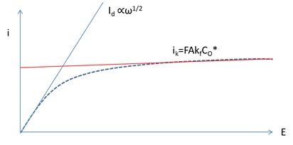
ik is defined by ik=FAKfCO*
the current potential profile is shown in Figure 5, which can be used to calculate k0 by fitting the high over potential region where the kinetics play a major role as shown by the linear function of ik. The low over-potential region produces a diffusion layer region whose current slop is proportional to rotation square root of angular velocity ω.
For more generation quasi-reversible system, the current potential curve of a RDE experiment is given by
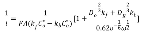
(10)

Example 3. RDE data taken at different rotation speeds for 10 mM aqueous solution of K3Fe(CN)6 in 0.1 M Na2SO4
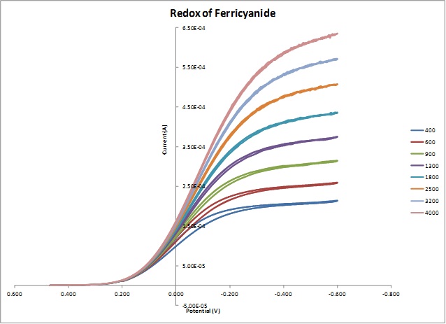
Note: All above experimental data were taken by students from Dr. Pan’s electrochemistry class in Fall 2014.
References: Electrochemical methods, fundamental and applications, 2nd edition, Allen J. Bard and Larry R. Faulkner. John Willey & Sons, Inc. 2001.